- 您现在的位置:买卖IC网 > Sheet目录477 > MICRF220AYQS TR (Micrel Inc)RCVR ASK/OOK 300-450MHZ 16QSOP
Micrel, Inc.
Electrical Characteristics (Continued)
MICRF220
Parameter
Condition
Min.
Typ.
Max.
Units
Demodulator
CTH Source Impedance,
Note 6
CTH Leakage Current In
CTH Hold Mode
f REF = 9.81713MHz
f REF = 13.52313MHz
T A = +25oC
T A = +105oC
165
120
1
10
k ?
nA
Digital / Control Functions
DO Pin Output Current
Output Rise Time
Output Fall Time
Input High Voltage
Input Low Voltage
Output Voltage High
Output Voltage Low
As output source @ 0.8 V DD
As output sink @ 0.2 V DD
15pF load on DO pin, transition time
between 0.1xV DD and 0.9xV DD
SHDN, SEL0, SEL1, SQ
SHDN, SEL0, SEL1, SQ
DO
DO
0.8V DD
0.8V DD
300
680
600
200
0.2V DD
0.2V DD
μA
ns
V
V
V
V
RSSI
RSSI DC Output Voltage
Range
RSSI Output Current
RSSI Output Impedance
RSSI Response Time
? 110dBm RF input level
? 50dBm RF input level
5k Ω load to GND, ? 50dBm RF input level
V SEL0 = V SEL1 = 0V, RF input power stepped
from no input to ? 50dBm
0.5
2.0
400
250
10
V
μA
?
ms
Notes:
1.
2.
3.
4.
5.
6.
Exceeding the absolute maximum rating may damage the device.
The device is not guaranteed to function outside of its operating rating.
Device is ESD sensitive. Use appropriate ESD precautions. Exceeding the absolute maximum rating may damage the device.
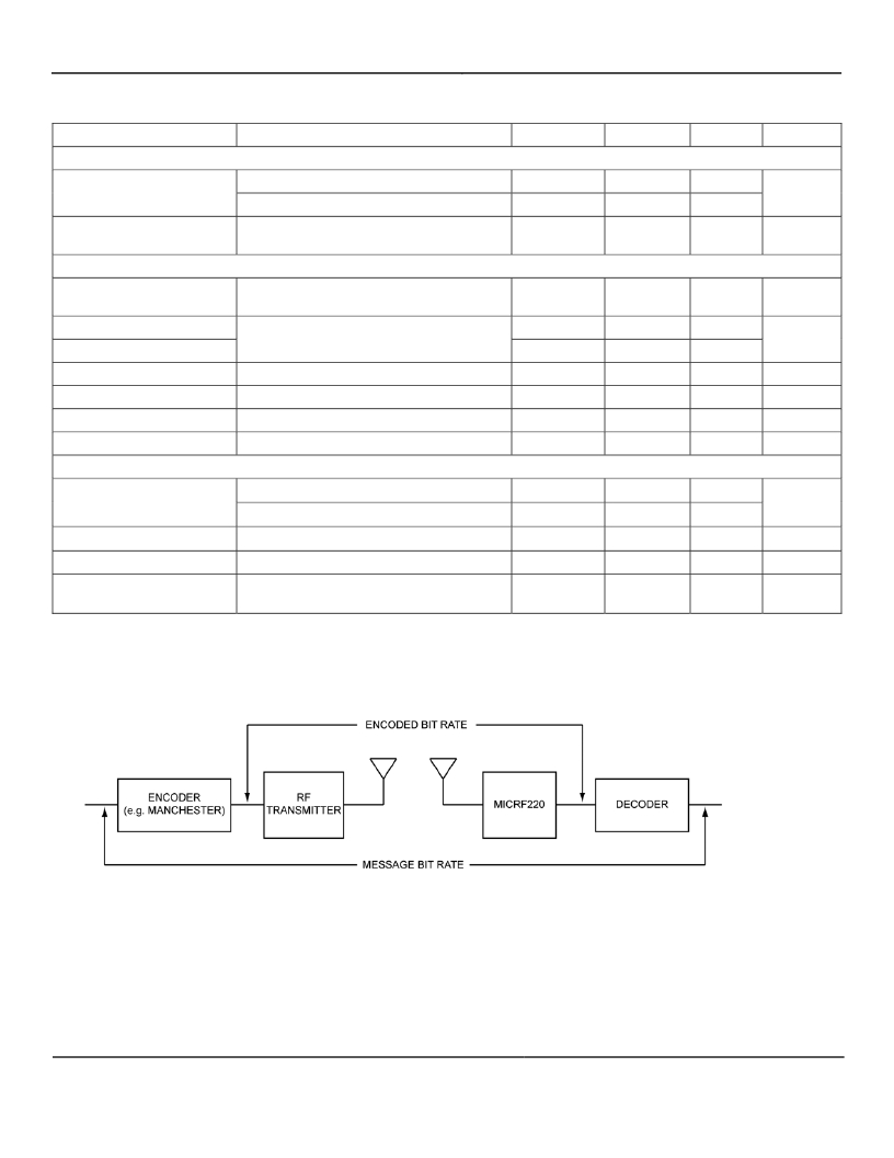
Encoded bit rate is 1/(shortest pulse duration) that appears at MICRF220 DO pin.
In an ON/OFF keyed (OOK) signal, the signal level goes between a “mark” level (when the RF signal is ON) and a “space” level (when the RF
signal is OFF). Sensitivity is defined as the input signal level when “ON” necessary to achieve a specified BER (bit error rate). BER measured with
the built-in BERT function in Agilent E4432B using the PN9 sequence. Sensitivity measurement values are obtained using an input matching
network corresponding to 315MHz or 433.92MHz.
CTH source impedance is inversely proportional to the reference frequency. In production testing, the typical source impedance value is verified
with 12MHz reference frequency.
August 2010
4
M9999-082610-A
发布紧急采购,3分钟左右您将得到回复。
相关PDF资料
MICRF221AYQS TR
IC RF RECEIVER QWIKRADIO 16-QSOP
MICRF300YC6 TR
IC AMP 100/1000MHZ LN SC70-6
MICRF500BLQTR
TXRX UHF 700-1100MHZ 44-LQFP
MICRF501BLQ TR
TXRX SGL 300-600MHZ 44-LQFP
MICRF505DEV1
KIT DEV RADIOWIRE 850-950MHZ
MICRF506DEV1
EVAL BOARD EXPERIMENTAL MICRF506
MICRF507YML TR
TXRX FSK LOW PWR W/AMP 32MLF
MICRF600DEV1
KIT DEV RADIOWIRE 902-928MHZ
相关代理商/技术参数
MICRF221
制造商:MICREL 制造商全称:Micrel Semiconductor 功能描述:3.3V, QwikRadio 850 MHz to 950 MHz Receiver
MICRF221AYQS
功能描述:射频接收器 850MHz to 950MHz, 3.0V to 3.6V, 9mA, 10kbps ASK Recdeiver with Auto-Poll and RSSI, Shutdown in 16-lead QSOP
RoHS:否 制造商:Skyworks Solutions, Inc. 类型:GPS Receiver 封装 / 箱体:QFN-24 工作频率:4.092 MHz 工作电源电压:3.3 V 封装:Reel
MICRF221AYQS TR
功能描述:射频接收器 850MHz to 950MHz, 3.0V to 3.6V, 9mA, 10kbps ASK Recdeiver with Auto-Poll and RSSI, Shutdown in 16-lead QSOP
RoHS:否 制造商:Skyworks Solutions, Inc. 类型:GPS Receiver 封装 / 箱体:QFN-24 工作频率:4.092 MHz 工作电源电压:3.3 V 封装:Reel
MICRF229YQS-T5
功能描述:- RF Receiver ISM 433.92MHz -112dBm 20kbps On-Board, Trace 16-QSOP 制造商:microchip technology 系列:- 包装:剪切带(CT) 零件状态:停产 频率:433.92MHz 灵敏度:-112dBm 数据速率(最大值):20kbps 调制或协议:ISM 应用:通用 电流 - 接收:6mA 数据接口:- 存储容量:- 天线连接器:板载,跟踪 特性:- 电压 - 电源:3.5 V ~ 5.5 V 工作温度:-40°C ~ 105°C 封装/外壳:16-LSSOP(0.154",3.90mm 宽) 供应商器件封装:16-QSOP 标准包装:1
MICRF229YQS-TR
功能描述:- RF Receiver ISM 433.92MHz -112dBm 20kbps On-Board, Trace 16-QSOP 制造商:microchip technology 系列:- 包装:剪切带(CT) 零件状态:停产 频率:433.92MHz 灵敏度:-112dBm 数据速率(最大值):20kbps 调制或协议:ISM 应用:通用 电流 - 接收:6mA 数据接口:- 存储容量:- 天线连接器:板载,跟踪 特性:- 电压 - 电源:3.5 V ~ 5.5 V 工作温度:-40°C ~ 105°C 封装/外壳:16-LSSOP(0.154",3.90mm 宽) 供应商器件封装:16-QSOP 标准包装:1
MICRF230YQS-T5
功能描述:- RF Receiver ISM 433.92MHz -112dBm 20kbps On-Board, Trace 16-QSOP 制造商:microchip technology 系列:- 包装:剪切带(CT) 零件状态:停产 频率:433.92MHz 灵敏度:-112dBm 数据速率(最大值):20kbps 调制或协议:ISM 应用:通用 电流 - 接收:6mA 数据接口:- 存储容量:- 天线连接器:板载,跟踪 特性:- 电压 - 电源:3.5 V ~ 5.5 V 工作温度:-40°C ~ 105°C 封装/外壳:16-LSSOP(0.154",3.90mm 宽) 供应商器件封装:16-QSOP 标准包装:1
MICRF230YQS-TR
功能描述:- RF Receiver ISM 433.92MHz -112dBm 20kbps On-Board, Trace 16-QSOP 制造商:microchip technology 系列:- 包装:剪切带(CT) 零件状态:有效 频率:433.92MHz 灵敏度:-112dBm 数据速率(最大值):20kbps 调制或协议:ISM 应用:通用 电流 - 接收:6mA 数据接口:- 存储容量:- 天线连接器:板载,跟踪 特性:- 电压 - 电源:3.5 V ~ 5.5 V 工作温度:-40°C ~ 105°C 封装/外壳:16-LSSOP(0.154",3.90mm 宽) 供应商器件封装:16-QSOP 标准包装:1
MICRF300-315 EV
功能描述:EVAL BOARD FOR MICRF300 制造商:microchip technology 系列:- 零件状态:无货 类型:放大器 频率:315MHz 配套使用产品/相关产品:MICRF300 所含物品:板 标准包装:1
